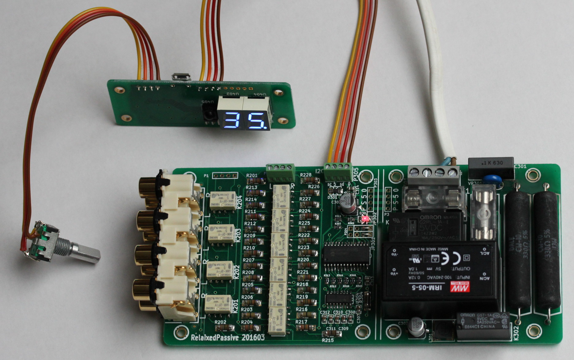
This RelaixedPassive is the latest of my RelaiXed designs. It is an audio volume control and input channel selector with a minimalistic passive design: there are are no active parts in the audio path: no transistors, opamps, tubes. It is a true attenuator, and it does not add any distortion to the audio signal. This attenuator design inherits important concepts of my earlier RelaiXed preamplifier designs:
The avoidance of clicks in the audio signal is the major improvement with respect to my original attenuator design of several years back, and distinguishes this design from relay-attenuators from some other sources. Note that a soft mechanical clicking noise is still emitted by the relays themselves.
This attenuator specifically targets the DIY high-end audio hobbyist, and aims at integration in the same cabinet with some power amplifier of your choice. Integration with a power amplifier avoids longer cinch cables and connectors at the output of the attenuator. Due to the relatively high output resistance of a passive volume control, passive attenuators in general are sensitive to cable quality and cable type. Integration with the power amplifier removes this sensitivity.
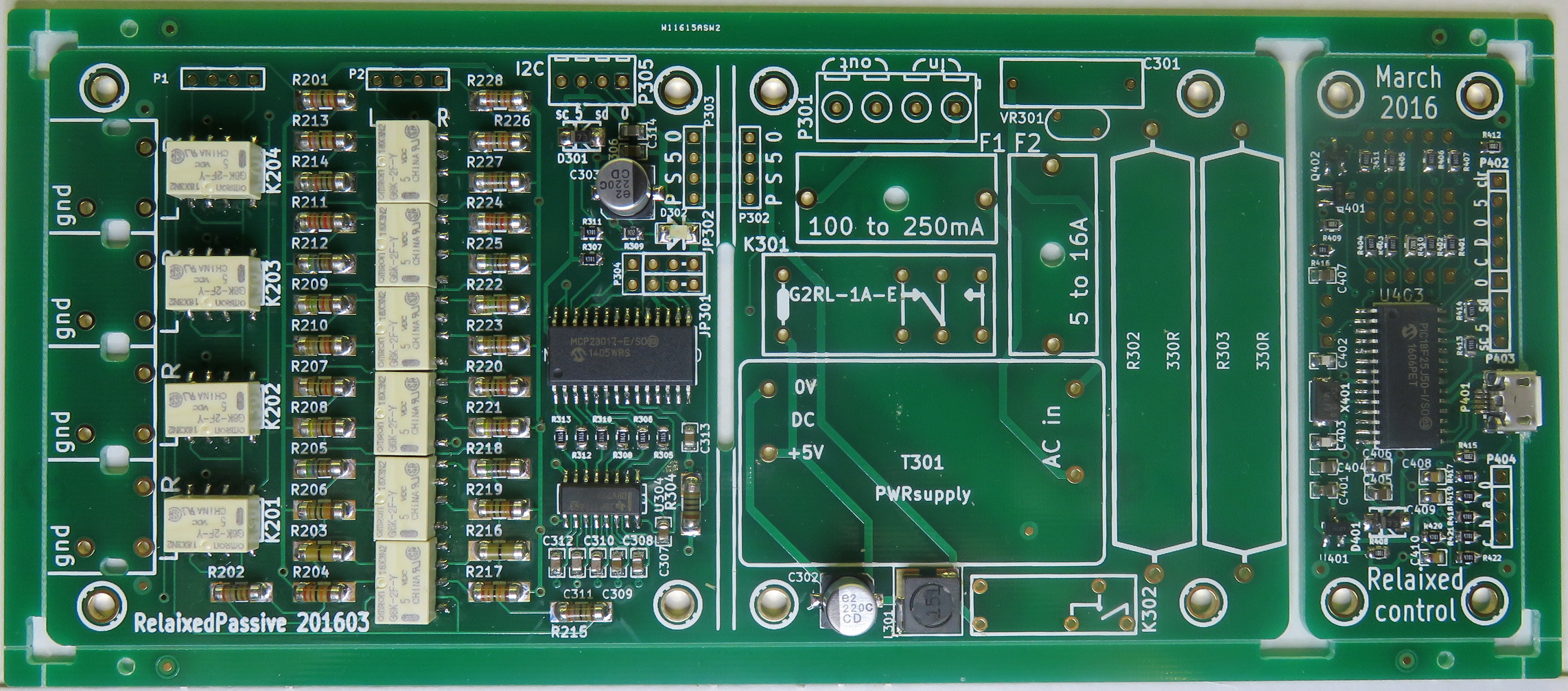
To take further benefit from the IR remote control in the amplifier integration, this design comes with remote control for the power switch, including soft-start functionality. Through a heavy power relay and tough power resistors, the soft-start mode supports the safe switching of large toroid transformers and/or large capacitor banks in your power supply. This avoids the need for the typical thermistors, that are used to reduce rush-in currents for larger transformers. The on-board small transformer for stand-by power, and the fuses for the control and the mains power output, simplify the wiring in your amplifier chassis. If you do not trust this mains power switching so nearby to the precious audio signals, the board allows you separate it into two parts: the audio attenuator versus the power supply and power switching. After separation, each board still provides 4 mounting holes, and 4 low-voltage wires are needed for their interconnection.
The main difference with the RelaiXed preamp is of course its passive nature, and the use of standard (single-ended, "RCA" cinch connected) audio as opposed to a balanced (XLR) design. Furthermore, this passive attenuator does not offer left-right balance control, which is available in the full Relaixed preamp.
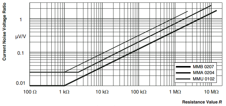
The resistors in the audio path are relatively large Vishay/Dale "MMB0207" professional MELF resistors. These are very good resistors for high-end audio, obviously surpassing the cheap smaller SMD resistors. Their quality can be seen for instance from their 'current noise' specification, rivalled by hardly any alternatives:
April 3, 2018: OUT OF STOCK
The PCBs for this design are out of stock.
To save on my own hobby-time, I will not provide support anymore on this design for new interested builders.
As dedicated audio hobbyist, you might re-produce a set of PCBs for yourself or a few friends. For that purpose,
see the information further down on Gerber files.
However, for commercial applications you shall ask me permission for re-use of this design.
September 7, 2019: KiCad design sources released
I do keep getting requests for this design, but I do not have the time to bring out and support these PCBs anymore.
To support the DIY hobbyist community, I decided to make the design sources available.
So now, you can more easily update the design to your preferences and create your own version.
This RelaixedPassive is designed with the open-source KiCad tooling.
I have ported the final/latest September 2016 version of the design files into the current KiCad version 5.
These design files contain both the schematics and the layout. Create your KiCad project by downloading and unpacking
this zip file,
enter its 'KiCad5-201609' directory, and open its 'relaixedPassive.pro' project file with KiCad.
The revision shown here is of July 2016, and has some small updates with respect to the 2014 design. The current version has a smaller front control PCB and a modified stand-by power-supply. The audio section and relay control remained unmodified. The design information of the earlier version is still available.
For documentation, you can look into:
The design does support larger multi-channel multi-board configurations, where a single front unit controls several audio/relay boards. In a multi-board set-up, only one of the boards needs to have the power supply. Such set-up can be used for different applications:
When different i2c bus addresse are not used, all connected relay boards will just behave identically in lock-step mode.
| Output audio connectivity: | One stereo audio signal through a 4-pin screw connector |
| Input audio connectivity: | Four stereo inputs, typically through an on-board 4x2 cinch (RCA) connector block |
| Input resistance: | 27Kohm (can be reconfigured to any other value) |
| Output resistance: | 0 to 13Kohm, varies with the volume selection |
| Frequency bandwidth: | DC to 150kHz (-3dB) at 10dB attenuation, |
| Left/Right channel separation: | 96dB at 1 kHz and 10dB attenuation |
| Input select attenuation: | 123dB from neighbouring input at 1kHz and 10dB attenuation |
| Power consumption during standby: | < 0.1 W |
| Power consumption in operation: | < 2 W |
| Maximum power switch to external load: | 16A, 240Vac |
| Maximum energy to absorb in soft-start: | 1000 Joules |
| Size of main PCB: | 150x74mm. Height above PCB surface: 27mm with RCA block, 22mm without |
| Size of front PCB: | 26x74mm. (For more sizes see the schematics document) |
The manual provides a table with an alternative set of resistor values for the attenuator to configure a 10Kohm input resistance. Other values can be chosen with the help of the online calculator.
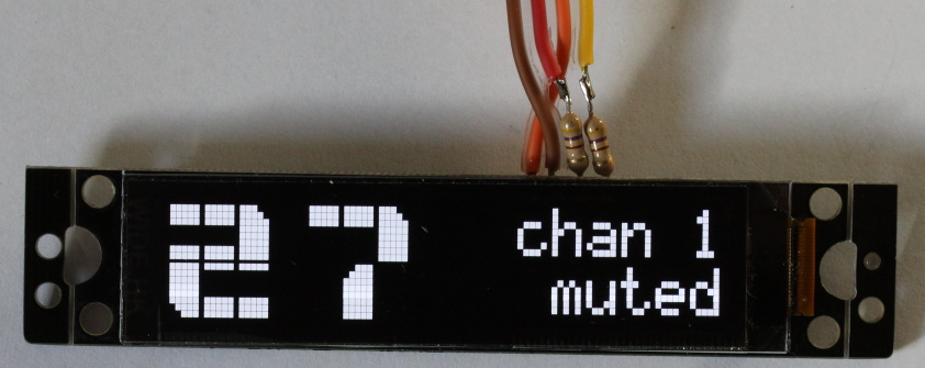
Support was added for a 16x2 character OLED display, as alternative for the standard 2-digit 7-segment display. This particular display from ebay was selected. Obviously, such OLED displays have a great contrast. Its i2c interface is simply connected in parallel on the 4-wire communication bus between the front- and the main- (relay) PCB. To use this display, you would need to update the firmware inside the PIC microcontroller to -at least- the 20160910 revision, which can be downloaded from the project sourceforge site. This display seems to have issues in obtaining a reliable communication. See how to handle that in the User Manual.