
The circuit contains 16 resistors and 16 switches, exactly 1 switch is closed at any setting.
This page provides background information to construct controllable attenuators for electronic signals, in particular targetting audio volume control. Different circuits are shown with their pros and cons.
Alternatively, you might want to check out neighbouring web pages for:
The traditional potentiometer is implemented with an electrical contact that slides over a resistive layer. An example of a well-known audio-grade potmeter is the Alps Blue.
A high-end (good and costly) alternative is the rotary switch. This device consists of a series of discrete resistors and switches, of which always one switch is actually closed. Resistor-switch networks can offer advantages over the potentiometer such as:
Good audio attenuator rotary switches are made for instance by
DACT.
An impressive DIY rotary attenuator is
here.
It is special in using two decks of switches and two sets of resistors per channel.
Nice switches and resistors are available for instance at
www.triodes.nl.
Of course there are integrated circuits that implement a similar functionality, and where the mechanical switches are replaced by MOSFETs. See for instance National and Cirrus. Clearly such devices allow nicely compact solutions. However, for truly high-end audio, I do not trust the sound quality of such devices due to the non-linear parasitic capacitances in such switches.
This page focusses on an alternative solution, using discrete resistors and relays as switches. While maintaining the advantages of the rotary switches, the relays offer improved options for remote control of the attenuation, and the solution becomes trivially extendible to handle multi-channel control. Furthermore, the use of small mass-produced relays promises great quality-for-money for DIY audio enthousiasts. This is an example of such a project. A nice design is dicussed in this diyAudio thread.
Below, different circuits are presented. To obtain concise drawings and a fair comparison,
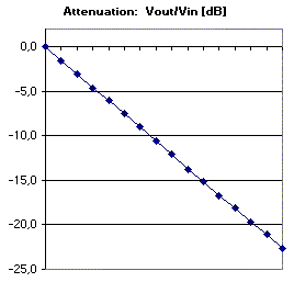
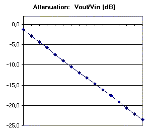
all circuits are constructed to provide (just) 16 volume levels, with steps of 1.5dB,
and with an impedance level of about 100Kohm.
Remind that for audio volume control you want a logarithmic scale, that means that for
every successive step the signal amplitude should be scaled by a constant factor,
or in other words, every step scales the amplitude with a fixed number of dBs.
Such scaling gives a human impression of 'linear' sound level steps.
(Note that the relay network in above link does not adhere to this property,
but constant-voltage steps are made instead.)
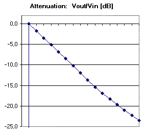
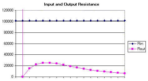
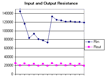
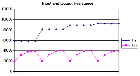
For characterization the following properties are shown:
You might believe that, depending upon relay quality, the audio signal quality can degrade when passing through multiple (closed) contacts. Open contacts normally have such high impedance (low capacitance) that they will not affect audio quality. Similarly, having many resistors (and solder joints) might affect quality. Of course, the number of restistors and switches has a cost implication.
This circuit is similar to what is implemented in rotary-switch attenuators,
and is in impedance behavior similar to a potentiometer.

The circuit contains 16 resistors and 16 switches,
exactly 1 switch is closed at any setting.
|
|
This circuit is similar to the 'R-2R' ladder networks as used in D-A conversion,
but modified to make exponential voltage steps in stead of linear steps.
The 16 settings are obtained by closing the switches according to a 4-bit
binary counter, with the most significant bit controlling Q1.
The first stage (around Q1) creates a constant output resistance of 25Kohm.
This resistance is kept constant between every stage.
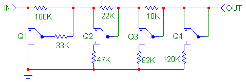
The circuit contains only 7 resistors and 4 switches,
all 4 switches might simultaneously carry audio current.
|
|
Allow only two switches to simultaneously carry audio current,
and reduce the number of components in comparison with the rotary switch circuit:
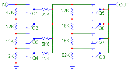
This circuit is designed to close exactly 1 switch of the first stage
and one switch of the second stage. The first stage implements steps of -6dB,
the second stage makes steps of -1.5 dB.
It counts 11 resistors and 8 switches, of which 2 can simultaneously carry audio current.
|
|
You can analyze your own circuit diagram, and generate the same kind of figures with the program provided on this separate page...
For actual implementation you probably want more than 16 steps, reaching lower than -24 dB. The above circuits are not hard to extend, but on interest I could publish such schematics here.
For high-end audio application, you need good quality small-signal relays.
Some older, larger, relays which I had lying around did not perform satisfactory.
After going through datasheets, I bought a set of
NAIS TQ2
relays. These small (DIP) relays behave nicely transparent. They are easily available at many sites
for prices between $1.50 and $7 (for instance
here).
For a stereo 32-step 'logarithmic ladder' you would need only 5 of these.
(I assume that other quality small-signal relays will be fine as well,
such as the
OMRON G6K.)
To control the relays one can create hardwired logic. The more advanced hobbyist could use a microcontroller like a PIC 16F88 or 16F818. This allows an implementation with very few components, and direct attachment of an infra-red receiver for a remote control. Next to that, a simple (mono linear) potentiometer can be attached which operates on DC only, of which the DC slider voltage is read by the PIC A/D converter, to control the relays also manually. To buffer the PIC outputs to the relays, an additional IC like the ULN2003 is nice to have.
PS: For other circuit design ideas and tools see
Greg's circuit page.
Jos van Eijndhoven, January 2004
![]()
Back to my home page
-- This page was constructed with the freeware
1st page 2000 html editor